How radios work
This page covers radios, the several different types, and their principles of operation, to enable you to go a little deeper than visual fault finding.
Summary
Often, radios can be fixed simply by looking for the sort of problems common to all electronic gadgets, with very little idea of how they actually work. But when that approach fails, it's necessary to have a basic grounding in the theory of operation in order to go deeper. This page aims to provide that grounding, describing the several types and their principles of operation.
We start by looking at the basic theory of radio transmission, then go on to examine how that theory is put into practice in several different types of radio.
A separate page on Portable radios covers the practical aspects of diagnosing and fixing radios.
Basic radio theory
In theory, you might be able to connect a microphone, through a powerful amplifier, directly to a transmitting aerial. In practice that wouldn't work because (for reasons we'll come to) you'd need an aerial many miles long, and there'd be no way to transmit more than one programme at a time without them getting mixed up.
An Audio Frequency (AF) signal, such as comes out of a microphone or could be fed into a loudspeaker, consists of frequencies in the range 20Hz - 20kHz (20 - 20,000 vibrations per second). In order to transmit it, that signal has to be impressed in some way upon a much higher Radio Frequency (RF) "carrier". There are several ways of doing that, the process being known as "modulation". A radio receiver essentially has three jobs to do: selection of the station you want to listen to and rejection of all the others ("tuning"), recovering the audio signal from modulated RF ("demodulation"), and amplification of the weak signal from the aerial in order to drive a loudspeaker or headphones. Tuning obviously has to be done before demodulation, but amplification is often performed before, between and after the other two functions.
We'll start by looking at several methods of modulation, then explain how tuning is achieved.
Amplitude Modulation (AM)
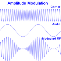
The simplest form of modulation is Amplitude Modulation, or AM. As shown in the diagram, the audio (AF) signal is impressed on the RF carrier as changes in amplitude.
Demodulation is simple. If you were to feed the modulated RF directly into a loudspeaker, you would hear nothing as it's positive just as much as it's negative and oscillates between the two far too fast for a loudspeaker or headphones to respond to. But if you chop off all the negative bits and average out the positive bits that are left, the result will follow the original AF signal which the speaker can then reproduce.
A disadvantage of AM is that it's susceptible to interference from things like a sparking electric motor, a car's ignition system or the fridge turning on and off. These all generate spikes of amplitude which the loudspeaker reproduces as clicks.
Frequency Modulation (FM)
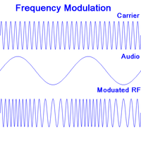
In Frequency modulation or FM, the amplitude of the carrier remains the same but the frequency is varied in sympathy with the audio signal, as shown in the second diagram. There are several methods of demodulation and these are generally slightly more complicated than for AM but fortunately we don't need to go into them for the purposes of repair.
An advantage of FM is that any spikes in the signal from interference can simply be chopped off by limiting the amplitude to a maximum value, with the result that they will hardly be heard in the audio output.
Digital Modulation
In digital radio (DAB, or Digital Audio Broadcasting) the audio signal is first converted to digital: the amplitude of the signal (or each channel in the case of stereo) is sampled, measured and converted to a binary number many times per second. The absolute minimum rate or sampling is twice for every cycle of audio, so for sound containing frequencies up to 20kHz the minimum "sampling rate" as it's called is 40,000 samples per second.
This produces rather a lot of data, but since each sound wave typically only differs slightly from the previous one there is much scope for data compression. This is done by a codec (coder-decoder).
Error correction bits are added to the compressed output of the codec allowing short sequences of corrupted bits to be corrected at the receiving end, and longer sequences to be detected. The resultant data streams from a number of different programmes are then multiplexed together creating an "ensemble" which is used to modulate a carrier.
A digital receiver simply performs all these processes in reverse.
DAB+ is a newer variant which uses a more efficient codec and more powerful error correction, allowing more programmes to be broadcast in a single ensemble. Whilst it allows successful reception of a weaker signal, there is a sharper "cliff edge" where a weak signal degenerates into a burbling noise before being lost.
Types of Radio
Tuned Radio Frequency (TRF)
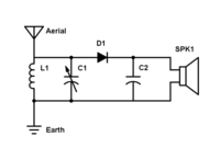
A crystal set is the simplest practical type of radio, and demonstrates some of the basic principles, except that it provides no amplification, relying entirely on the energy delivered by the aerial. The diagram shows a very simple crystal set.
The signal picked up by the aerial is passed to the coil or inductor L1 and the tuning capacitor C1, which form a "tuned circuit". The capacitor stores electrical energy much like a spring stores mechanical energy, and the inductor provides a kind of momentum to a flow of current like the momentum of a heavy object in motion. Just like a weight suspended by a spring, or a pendulum, or a guitar string, the inductor and capacitor have a particular resonant frequency, and tend to reinforce any signal of that frequency coming from the aerial, at the expense of other frequencies. (The arrow through the C1 symbol indicates that it's a variable capacitor, adjustable by a dial on the front panel.)
The diode D1 performs the demodulation, passing current in one direction only. The RF fluctuations are smoothed out by the capacitor C2 leaving us with the original audio signal which is fed to the headphones SPK1.
The Boy's Book of Crystal Sets is from another age but gives a more detailed yet very simple explanation of a crystal set, well worth looking at, whatever your gender!
Apart from poor sensitivity due to the lack of amplification, a crystal set also has poor selectivity, meaning that nearby stations are not well discriminated and a strong station still to be heard while trying to tune in to a nearby weak station. There are two reasons for this: firstly, there is only a single tuned circuit, and secondly, energy is drawn from that tuned circuit to drive the headphones, which causes its resonanant frequency to be less well defined.
Amplification can be added either to the RF signal before demodulation, or to the AF signal afterwards, or more usually both. If stages of amplification are added before, then additional tuned circuits can be added before, between and after the stages to improve selectivity. A difficulty arises, though, in that all the tuned circuits must track one another closely as you turn the tuning knob, making it increasingly difficult to design a radio with more than 2 or 3 separate tuned circuits.
Superhet
The vast majority of AM and FM radios follow the superhet design, which overcomes the problem of needing to make multiple tuned circuits track one another.
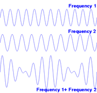
If two different frequencies are combined, sometimes they will be in step and reinforce each other and at other times they will be out of step and cancel, as shown in the diagram. So if for example two musical instruments are playing together, one at 440Hz and the other at 441Hz, once per second they will be in phase, and in between they will gradually go out of phase before coming back in phase again, like two people walking side by side with one taking slightly longer paces than the other. So you will hear the two notes "beating" against one another with a beat frequency of 1Hz, which is the difference between the two frequencies.
The effect is also known as a heterodyne. A superhet receiver (it should really be called an ultrahet, but never is) relies on creating an ultrasonic heterodyne between the incoming RF signal and another signal of different frequency generated within the receiver.
A local oscillator produces a signal which can be tuned to a frequency which differs from the frequency of the station you want to receive by typically (for AM) 455kHz. This produces a beat frequency of 455kHz which can then be amplified and tuned by as many tuned circuits as the designer wants, each tuned to a fixed frequency of 455kHz. As a result any station can be tuned by converting its frequency in this way to 455kHz, known as the Intermediate Frequency or IF, since it comes between the RF and the AF. Neat!
In the case of an FM receiver the RF is much higher frequency so an IF of 10.7MHz is normally used. An AM/FM receiver has both 455KHz and 10.7KHz tuned circuits in its IF stages, allowing it to work equally well for both bands.
In fact, if you mix two frequencies f1 and f2, you get not only f1 - f2 but also f1 + f2. This means that there would be a second frequency that would be converted to the same IF frequency and possibly cause interference. To avoid this there is normally a single tuned circuit and stage of amplification to filter out any such "ghost" stations before the mixer. This tuned circuit has to track the local oscillator frequency, but that's still easier than tracking several more tuned circuits as a TRF radio would have to.
In a reasonably modern receiver with push-button tuning (such as a car radio), a digital circuit replaces the local oscillator. This generates a precise frequency derived digitally from an accurate quartz crystal oscillator.
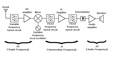
The diagram above gives a functional description of a typical superhet receiver:
- The aerial feeds into a tuned circuit and often a single stage of amplification.
- The mixer combines the signal with the output of a local oscillator to generate the IF.
- The IF stages consist of one of more stages of amplification and with further tuned circuits.
- A demodulator (AM or FM or both) recovers the AF.
- A power amplifier further amplifies the signal in order to drive a loudspeaker.
Digital
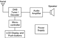
The diagram shows the essentials of a DAB radio. The intricacies of the DAB tuner and decoder are normally hidden within one or more integrated circuits protected by a metal screen. The RF goes in one end and the AF comes out of the other and everything in between is hidden. An audio amplifier driving the loudspeaker is generally distinguishable as a separate module. A microcontroller detects depressions of the push-buttons, drives the LCD display, and sends digital tuning controls to the DAB module. The power supply takes the battery or mains power and delivers a precise voltage (typically 3.3V or 5V) needed by the digital circuits as well as usually a higher voltage for the autio amplifier.
Software Defined Radio (SDR)
With the rapid advances in processing power seen in recent years many functions in everything from cars to washing machines and toasters, previously performed by single purpose mechanical or electrical designs have been taken over by software. Radios are no exception.
In a Software Defined Radio or SDR, the signal from the aerial is converted to digital form by a Digital to Analogue Converter (DAC) and the resultant stream of data is processed by software to perform the functions of tuning and demodulation. Using this approach, a radio can be made to receive AM, FM, DAB radio, digital or satellite TV, Morse code even, or any of a multitude of different digital formats such as WiFi, Bluetooth, GPS all just by changing the software.
Despite the extraordinary power of modern processors it's still not normally practicable to connect the aerial direct to the DAC. For a start, the signal would be far too weak. Also, the cost of a DAC rises sharply as you seek faster sampling rates so directly digitising a signal in the GHz range would normally be infeasable at reasonable cost.
For these reasons some analogue circuitry is retained. This not only amplifies the signal but also converts it to a more manageable range of frequencies using the superhet principle described earlier. So if you have a DAC with a maximum sample rate of 50 million samples per second (hence capable of directly digitising frequencies up to 25MHz) you can make an SDR which can receive signals within 25MHz of your local oscillator frequency, which itself can be chosen or tuned over an unlimited range of freqencies.
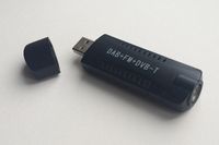
The USB TV dongles available very cheaply contain a pre-amplifier, local oscillator, mixer and DAC. Plugged into a computer loaded with suitable software, this comprises an SDR. Indeed, alternative software is available making it possible to experiment with your own SDR and receive signals of various types over a wide range of frequencies.
Perhaps the most dramatic and impressive recent example of an SDR is the Event Horizon Telescope. This imaged the super-massive black hole at the centre of galaxy M87 by combining and processing the digitised outputs of 10 radio telescopes across the globe using highly sophisticated software.
Frequency, Wavelength, Wavebands and Aerials
Frequency vs wavelength
Sometimes the frequency of a radio station is given, other times its wavelength. There is a simple relationship between the two.
Radio waves (and light) travels at 300 million metres per second. So if you were to count 300 million radio waves passing you per second (i.e. they have a frequency of 300MHz) then each peak must be racing past you just a metre behind the previous one. This is the wavelength - the distance between successive peaks (or troughs).
So if you multiply the distance between each wave and the next (the wavelength) by the number of them passing you per second (the frequency) we get the speed of light (or radio waves). Alternatively you can divide the speed of light by the frequency to get the wavelength, or by the wavelength to get the frequency.
Wavebands
The frequency spectrum is by convention divided into the following bands:
- Long Wave (LW) 150 - 285kHz (2000 - 1053m)
- Medium Wave (MW) 525 - 1605kHz (570 - 187m)
- Short Wave (SW)1.8 - 30MHz (167 - 10m)
- VHF 40 - 300MHz (7.5 - 1m)
- UHF 300MHz - 3GHz (1m - 10cm)
AM radio occupies the Long and Medium wavebands.
FM radio is transmitted in the VHF band in the range 88 - 108MHz.
DAB radio is also transmitted in the VHF in the range 175 - 240MHz.
Long waves are getting towards being comparable in length to the curvature of the earth, and so to an extent they can bend over the horizon. As a result they can be received at distances of many hundreds of miles. Much shorter wavelengths allow little more than line-of-sight communication.
In between, Short Waves don't bend well over the horizon yet can be received over distances of thousands of miles. This is because they can be reflected back and forth between the earth and the ionosphere (an ionised and electrically conductive layer of the atmosphere at altitudes of tens to hundreds of miles).
Aerials
A radio aerial works best if its length is half the wavelength of the stations it needs to receive. This is quite impracticable for Long and Medium wavebands but moving towards the upper VHF and into the UHF bands it becomes quite a manageable length. The multiple element TV aerials on roofs and chimneys consist of half-wavelength rods.
In the early days of radio, an aim was to put up the longest possible aerial in order to get good LW and MW reception. Since the days of portable transistor radios a ferrite rod aerial has invariably been used for these bands.
This consists of a magnetic but non-conductive rod of a ceramic material (ferrite) typically with two coils of wire around it, one for Medium Waves and the other for Long Waves. The ferrite rod has the effect of concentrating the magnetic component of the radio waves causing it to induce a signal in the coils. (Radio waves consist of interlinked waves in the electric and magnetic fields.) It has to be non-conducting as otherwise the radio waves would induce a current in the rod itself rather than in the coils around it. The ferrite rod aerial is very obvious if you open any AM radio.
