Power supplies: Difference between revisions
No edit summary |
|||
| Line 51: | Line 51: | ||
====Operation==== | ====Operation==== | ||
====Fault Finding==== | ====Fault Finding==== | ||
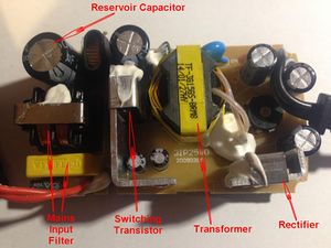
[[file:Img_0546a.jpg|thumb|right|Switching mode power supply - top]] | |||
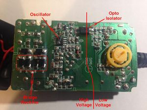
[[file:Img_0545a.jpg|thumb|left|Switching mode power supply - bottom]] | |||
Revision as of 09:46, 25 February 2016
Power supplies: theory, diagnostics and fixing.
Summary
Many pieces of electronic equipment include a power supply unit (often abbreviated to PSU) to convert the incoming electrical power from the mains or a battery to the form needed. This can involve the control and conversion of a relatively large amount of power in a fairly small space and some of the power will be wasted as heat. Heat can lead to failures.
Safety
- Mains driven power supplies can be dangerous to work on unless you fully understand what you're doing. They often contain large capacitors which can store dangerous voltages even after you've disconnected the mains supply.
Why is a power supply needed?
A power supply performs some or all of the following purposes:
- Voltage conversion: The mains electricity supply is 240v, which is much too high for most electronic gadgets and is dangerous if fingers might be exposed to it, so a voltage reduction may be required. In a few cases (e.g. a microwave oven or the supply to a camera flash tube), conversion to a higher voltage is required.
- Isolation: Even though the voltage might be reduced, if there remains a direct electrical path to the mains it can still be dangerous. Professional power tools, especially if used outdoors, are often powered through an isolation transformer in order to break that path.
- Rectification: The mains supply is AC, which means it reverses direction 100 times per second. Whilst this is fine for heating, some forms of lighting and most electric motors, electronics normally requires DC, which just goes in one direction. Rectification is the technical term for AC to DC conversion.
- Smoothing: AC momentarily drops to zero as it reverses direction, and if you simply rectify it, it will still be dropping to zero 100 times per second. This may be fine for example if you're just using it charge a battery, but electronic equipment generally can't cope with this. In audio equipment, for instance, it would cause a very loud buzz which would obliterate the music. Smoothing stores electrical energy to fill in the gaps and smooth the flow, a bit like the way the silencer on a car smooths the exhaust flow to make it quieter.
- Regulation: If the input mains voltage varies, the rectified and smoothed output will vary in proportion. If the power is supplied by a battery its voltage will drop as it is exhausted. The output voltage may also fall as you take more and more current. And unless large and expensive smoothing components are used, there will remain a certain amount of "ripple" which can cause an annoying hum in audio equipment. Electronic equipment often needs a supply which is not only very smooth but a fairly precise voltage in order that the design may be optimised. Regulation provides this. There are two kinds of voltage regulator:
- In a linear regulator, excess input power is simply absorbed and turned into heat, just a little if the excess is small or more if it's greater. This is a bit like keeping your foot on the accelerator of your car and controlling your speed with the brake. It's wasteful but cheap, nevertheless it may be good enough for low power devices unless they need to squeeze the maximum life out of a battery.
- In a switching regulator the power is switched on and off up to a few million times per second, with the on-time continually adjusted to compensate for variations in the input or in the power drawn by the load. This is like a room thermostat which is on for a greater proportion of the time the colder it is outside, in order to maintain a roughly constant indoor temperature. Just as the thermal inertia of the room smooths out the temperature variations as the thermostat switches on and off, the output of a switching regulator needs to be smoothed. However, the smoothing components can be very much smaller than are required for smoothing rectified mains as they only need to store energy for typically a few millionths instead of a hundredth of a second. A small coil is generally used which stores the energy as magnetism. A well designed switching regulator can be made very efficient, but is more complicated and more expensive than a linear regulator.
A switching-mode power supply as used with a laptop or in a phone charger generally includes all of the above elements but not in the same order. The raw mains input is rectified and roughly smoothed, giving mains voltage DC. This is then fed into a switching regulator. The switching regulator includes a transformer to provide isolation as well as to reduce the voltage to a more manageable level. Since the transformer is operating at a very high switching speed it can be much smaller than a mains transformer handling the same power, since it's transforming the power in very much smaller bites. Without a bulky mains transformer containing a lot of iron and copper, a switching-mode power supply can be made much lighter and more compact. In fact, it can often be made cheaper as the cost of modern electronics may be less than the cost of the iron and copper it replaces.
Theory and operation of power supplies
Linear Power Supplies
Operation
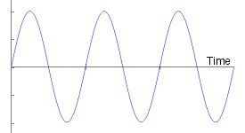
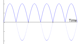
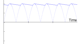
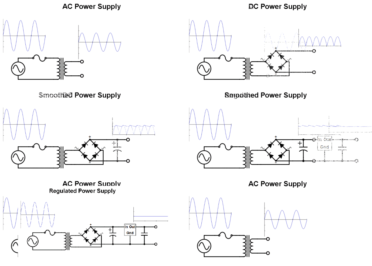
The animation above shows the various levels of sophistication of a linear power supply. Linear power supplies designed to run off the mains contain an iron cored transformer to provide isolation and voltage reduction and further components as required.
- An AC power supply just contains the transformer, and maybe a fuse (shown on the input to the transformer). The transformer has 2 windings: the primary connected to the mains, and the secondary connected to the output and generally delivering a much lower voltage. You will rarely see a power supply as simple as this as most low voltage equipment needs DC, not AC.
- A DC power supply sees the addition of a rectifier, generally consisting of 4 diodes (possibly in a single package with 4 leads) forming a bridge rectifier. The output of this is far from constant, but at least it only goes in one direction, so is good enough for a very simply battery charger.
- A smoothed power supply adds a capacitor which stores electric charge during the peaks and delivers it in the gaps between the cycles, and hence is often referred to as a reservoir capacitor. This will always leave a ripple on the output but a big enough capacitor may make it acceptably small.
- A regulated power supply additionally contains a linear regulator. This not only removes the ripple, but also gives a fairly precise output voltage even if the mains voltage varies.
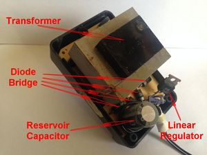
The photo shows a smoothed power supply which has been hacked with the addition of a linear regulator.
Sometimes you will find a power supply split into two parts, for example with a wall cube plugging into a mains socket and containing a smoothed power supply, and a linear regulator in the equipment itself.
Fault Finding
Fault finding in a linear power supply is straightforward once you understand how it works. You could follow these logical steps:
- First perform a visual check. Are the mains plug and lead in good condition, with no signs of cracked or damaged insulation? Are there any visible signs of overheating or burning, in particular of the transformer? Check the reservoir capacitor for any signs of bulging or leakage. Was there any burning or overheating smell when it stopped working?
- Test the fuse, and check for continuity from each of the live and neutral pins on the mains plug through to the transformer.
- Test each of the 4 diodes with a test meter on the diode range. In the case of a diode bridge in a single package, test between each of the AC inputs and each of the positive and negative outputs.
- If you can, test the reservoir capacitor. You may be able to test it in-circuit with a capacitor tester but you will get a more reliable result if you can unsolder it. (Some test meters have a capacitance range.)
- Plug the power supply in, first making sure there is no danger of anyone touching exposed mains on the mains side of the transformer. Perform the following tests:
- With a test meter on an AC voltage range, check that the voltage on the secondary of the transformer (or the input to the bridge rectifier) is reasonable.
- With a test meter on a DC voltage range, check that the voltage on the output of the bridge rectifier, or across the reservoir capacitor is reasonable.
- With a test meter on a DC voltage range, check the output of the linear voltage regulator.
Switching Mode Power Supplies
This section is work in progress
