Connecting and joining wires: Difference between revisions
No edit summary |
No edit summary |
||
| (17 intermediate revisions by 3 users not shown) | |||
| Line 1: | Line 1: | ||
This page covers how to safely and reliably connect, splice or join wires together. | This page covers how to safely and reliably connect, splice or join wires together. | ||
<div class="showtoc"> | |||
__TOC__ | |||
</div> | |||
==Summary== | ==Summary== | ||
| Line 8: | Line 11: | ||
===Safety=== | ===Safety=== | ||
[[File:Warning03.png|30px|left]] | [[File:Warning03.png|30px|left]] | ||
::Where the wires carry mains voltage it's essential that the join is properly insulated | ::Where the wires carry mains voltage it's essential that the join is properly insulated and the wires clamped to prevent the join being strained. | ||
::Even if mains voltages are not involved then a [[Glossary:Short circuit|short circuit]] resulting from an uninsulated join may cause damage to other components. | |||
::Be aware that a poorly made join may heat up and even cause a fire. | |||
==Fix it before it breaks!== | ==Fix it before it breaks!== | ||
A very common fault is a broken headphone lead at the point where it enters the jack connector. If the outer insulation is starting to crack, you're on borrowed time! A simple solution is to repair it with Sugru. This comes in a mouldable putty-like form and sets within 24 hours to synthetic rubber. Mould a little around the cable to protect the damaged section, moulding it onto the connector to prevent movement and thinning progressively away from the connector so avoiding any point at which he cable can be sharply bent. | A very common fault is a broken headphone lead at the point where it enters the jack connector. If the outer insulation is starting to crack, you're on borrowed time! A simple solution is to repair it with Sugru. This comes in a mouldable putty-like form and sets within 24 hours to synthetic rubber. Mould a little around the cable to protect the damaged section, moulding it onto the connector to prevent movement and thinning progressively away from the connector so avoiding any point at which he cable can be sharply bent. | ||
==Screw and spring terminals== | ==Screw, clamp and and spring terminals== | ||
Probably the oldest method of connecting a wire is with a screw terminal. The screw head may hold the wire directly or preferably under a washer, or the screw may clamp the wire in a hole in a brass terminal. | Probably the oldest method of connecting a wire is with a screw terminal. The screw head may hold the wire directly or preferably under a washer, or the screw may clamp the wire in a hole in a brass terminal. | ||
| Line 31: | Line 35: | ||
===Choc block connectors=== | ===Choc block connectors=== | ||
[[File:Choc block connector.jpg|180px|thumb|left|A choc block connector. When using stranded wire, first twist the strands together (blue wire) then fold them over (red wire).]] | [[File:Choc block connector.jpg|180px|thumb|left|A choc block connector. When using stranded wire, first twist the strands together (blue wire) then fold them over (red wire).]] | ||
These come in strips which can be easily cut according to the number of wires you need to connect. They are useful for connecting low voltage wires but offer no form of cable clamp so you | These come in strips which can be easily cut according to the number of wires you need to connect. They are useful for connecting low voltage wires but offer no form of cable clamp so should only be used for mains if you can ensure that the cables cannot be strained. They contain a hole between each pair of connectors, which you can use to screw them down to a firm base. | ||
Choc block connectors come in various sizes such as 3A, 5A, 15A etc., but the only important thing is to ensure that they are big enough to take the wire, | Choc block connectors come in various sizes such as 3A, 5A, 15A etc., but the only important thing is to ensure that they are big enough to take the wire, and more importantly, the wire is big enough to be gripped by the screw. You can always strip a little extra insulation and fold the wire double to give the screw more to grip. | ||
Provided space allows, these connectors can be useful when replacing a thermal fuse which might be blown by the heat of a soldering iron. However, you may have to remove the housing, often made of soft plastic which may melt before the thermal fuse trips. | |||
===Spring terminal connectors=== | ===Spring terminal connectors=== | ||
[[File:Spring terminal connector.jpg|180px|thumb|right|A spring terminal connector.]] | [[File:Spring terminal connector.jpg|180px|thumb|right|A spring terminal connector.]] | ||
There are several types of these, and they can be used to make a quick and easy connection without any tools (except for stripping the insulation). They are often used for loudspeaker cables and in model train sets, providing a simple way for connections to be made or removed as often as needed. Applying solder to the bare end of stranded wire is helpful. | There are several types of these, and they can be used to make a quick and easy connection without any tools (except for stripping the insulation). They are often used for loudspeaker cables and in model train sets, providing a simple way for connections to be made or removed as often as needed. Applying solder to the bare end of stranded wire is helpful. | ||
[[File:Wago connectors.jpg|180px|thumb|left|A selection of Wago connectors.]] | |||
Wago connectors are a common proprietrary form of spring connector, coming in several different types. They are designed for commoning two or more wires, for mains or for low voltage use. Some have a lever to lift or to press to release the spring, but with others, you just push the wire in, and there's no visible means of releasing it. The trick with these is to twist the wire back and forth while pulling it firmly. | |||
==Soldering== | ==Soldering== | ||
Twisting the wires together and soldering is often the best method but the wires | [[File:SolderJoin-spliced.jpg|180px|thumb|right|A solder join - wires spliced together (preferred method).]] | ||
[[File:SolderJoin-twisted.jpg|180px|thumb|left|A solder join - wires twisted together (not so good).]] | |||
Twisting the wires together and soldering is often the best method, but there are two ways of doing this. | |||
If possible, you should twist the wires in-line before soldering as this makes a stronger (and neater) join than twisting the ends together. This requires a greater length to be stripped of insulation and can be tricky if the wires differ in diameter, or if one is stranded and the other solid. | |||
The wires need to be clean in order to make a good joint. A little extra flux from a flux pen never does any harm and often makes it easier if the insulation has not been freshly removed. In the case of enamelled wire, the enamel needs to be scraped or burnt off. If a little remains it often won't matter and may melt with the solder. In fact some wire enamels are "solder-through" and designed to melt with the solder, but an initial scrape to get it started usually helps. | |||
===Soldering headphone leads=== | |||
Headphone leads use a special kind of ultra-flexible wire consisting of many individually enamelled strands of fine wire. The three connections for stereo headphones or four for a stereo headset use different coloured enamel. You will need to separate the strands of each colour. | |||
The enamel may be designed to melt in the solder but it often helps to start it off by gently scraping with a knife, trying not to break any of the strands as you do so. Alternatively you may be able to burn off the enamel in a flame. | |||
===Heat shrink solder sleeves=== | ===Heat shrink solder sleeves=== | ||
A simple solution if you don't have a soldering iron handy is to use heat shrink solder sleeves. These contain a ring of low temperature solder in the centre of a heat shrink tube. Make sure the stripped ends of the wires are clean so as to accept the solder. Pass one wire in each end so that they cross over in the solder ring, then simply apply a heat gun. This simultaneously melts the solder and shrinks the sleeve to insulate the join. | A simple solution if you don't have a soldering iron handy is to use heat shrink solder sleeves. These contain a ring of low temperature solder in the centre of a heat shrink tube. Make sure the stripped ends of the wires are clean so as to accept the solder. Pass one wire in each end so that they cross over in the solder ring, then simply apply a heat gun. This simultaneously melts the solder and shrinks the sleeve to insulate the join. | ||
==Crimping== | ==Crimping== | ||
| Line 54: | Line 71: | ||
Some crimp connectors such as the one illustrated have a heat shrink sleeve. This can be recognised by the noticeably larger diameter of the sleeve at the two ends. When shrunk with a heat gun this seals around the wires at each end (provided they're not too thin), giving extra protection to the two wires being joined. | Some crimp connectors such as the one illustrated have a heat shrink sleeve. This can be recognised by the noticeably larger diameter of the sleeve at the two ends. When shrunk with a heat gun this seals around the wires at each end (provided they're not too thin), giving extra protection to the two wires being joined. | ||
Another type of crimp connector has a blind hole into which both wires to be joined are inserted together. | |||
'''N.B.''' for safety, always give a crimp connection good tug after making it to ensure it's a good one. | |||
===DIY crimping=== | ===DIY crimping=== | ||
| Line 59: | Line 80: | ||
An alternative is to use narrow gauge copper or brass tubing as available from model making suppliers. Choose a size into which the wire fits comfortably. Cut a short length by rolling it on a flat surface under the blade of a craft knife to score it and then snap it off. Insert one wire into each end and crush the tube onto each wire with a pair of fine-nosed pliers or blunt wire cutters (but if you use wire cutters, take care not to cut into the tubing). | An alternative is to use narrow gauge copper or brass tubing as available from model making suppliers. Choose a size into which the wire fits comfortably. Cut a short length by rolling it on a flat surface under the blade of a craft knife to score it and then snap it off. Insert one wire into each end and crush the tube onto each wire with a pair of fine-nosed pliers or blunt wire cutters (but if you use wire cutters, take care not to cut into the tubing). | ||
'''N.B.''' The tug test is arguably even more important with a DIY crimp. | |||
{| | {| | ||
|- style="vertical-align: top;" | |- style="vertical-align: top;" | ||
| Line 67: | Line 90: | ||
==Insulation displacement connectors== | ==Insulation displacement connectors== | ||
[[File:Scotchlok connector.jpg|180px|thumb|right|A Scotchlok connector.]] | [[File:Scotchlok connector.jpg|180px|thumb|right|A Scotchlok connector.]] | ||
Scotchlok connectors contain a piece of metal which cuts through the insulation and bites into the copper conductor. They are commonly used in auto electrics for splicing into power wires in order to supply after-market accessories. They contain two holes for two wires, one open at the side allowing it to be slipped over an existing wire, and the other a blind hole to take a lead to the accessory. Squeezing it with a pair of pliers causes the metal piece to cut through the insulation of both wires and make the connection. Folding over the flap allows you to lock it closed. | |||
You could equally use one of these to connect the ends of two wires, but you must use the right size for the wires you are connecting in order for it to cut fully through the insulation whilst not damaging the copper wire inside. | You could equally use one of these to connect the ends of two wires, but you must use the right size for the wires you are connecting in order for it to cut fully through the insulation whilst not damaging the copper wire inside. | ||
==Insulating your connections== | ==Insulating your connections== | ||
Some types of connector are self-insulating, so long as none of the uninsulated wire is exposed but with others you will usually need to provide some form of insulation. | Some types of connector are self-insulating, so long as none of the uninsulated wire is exposed, but with others you will usually need to provide some form of insulation. | ||
* PVC tape is the simplest and easiest but not necessarily the neatest. '''NEVER''' simply bind up a cracked mains lead with PVC tape. | * PVC tape is the simplest and easiest but not necessarily the neatest. '''NEVER''' simply bind up a cracked mains lead with PVC tape. | ||
* Heat shrink sleeving is an excellent method. It comes in a variety of sizes and colours, pre-cut or in a continuous length. Choose a size which is no more than twice the diameter of the joint you need to insulate, and don't forget to slip it onto one of the wires before you join them! If soldering, keep it away from the iron. | * Heat shrink sleeving is an excellent method. It comes in a variety of sizes and colours, pre-cut or in a continuous length. Choose a size which is no more than twice the diameter of the joint you need to insulate, and don't forget to slip it onto one of the wires before you join them! If soldering, keep it away from the iron. Once you're ready, slip it over the join and heat with a heat gun until it has fully shrunken. If you don't have a heat gun to hand, you can hold it very close above a soldering iron and it should shrink slowly, but be very careful not to let it touch the iron. | ||
* Sugru can be used to insulate a join as described [[#Fix_it_before_it_breaks.21|above]], such as in a headphone lead, but don't rely on it alone to provide strain relief. If you need strain relief then one solution would be to knot the lead either side of the join to give the Sugru something to hold onto. | * Sugru can be used to insulate a join as described [[#Fix_it_before_it_breaks.21|above]], such as in a headphone lead, but don't rely on it alone to provide strain relief. If you need strain relief then one solution would be to knot the lead either side of the join to give the Sugru something to hold onto. | ||
* The earth wire in the type of mains cables designed for permanent installation is often uninsulated. Green and yellow striped sleeving is available to slip over this within a mains socket or wall switch to prevent it touching a live connection. This will sometimes be useful in other circumstances, but avoid using it where might confuse the next repairer into thinking it's an earth wire when it isn't. | * The earth wire in the type of mains cables designed for permanent installation is often uninsulated. Green and yellow striped sleeving is available to slip over this within a mains socket or wall switch to prevent it touching a live connection. This will sometimes be useful in other circumstances, but avoid using it where might confuse the next repairer into thinking it's an earth wire when it isn't. | ||
[[Category:Skills]] | |||
[[Category: | |||
Latest revision as of 21:27, 9 October 2022
This page covers how to safely and reliably connect, splice or join wires together.
Summary
Often during a repair, wires need to be connected or reconnected. Perhaps a worn out flex is being replaced or a failed thermal fuse. Simply twisting the wires together would hardly ever be a good idea, but there are several other ways of doing it.
If you are regularly doing repairs then you may find it useful to keep a few connectors of different types in your tool box.
Safety
- Where the wires carry mains voltage it's essential that the join is properly insulated and the wires clamped to prevent the join being strained.
- Even if mains voltages are not involved then a short circuit resulting from an uninsulated join may cause damage to other components.
- Be aware that a poorly made join may heat up and even cause a fire.
Fix it before it breaks!
A very common fault is a broken headphone lead at the point where it enters the jack connector. If the outer insulation is starting to crack, you're on borrowed time! A simple solution is to repair it with Sugru. This comes in a mouldable putty-like form and sets within 24 hours to synthetic rubber. Mould a little around the cable to protect the damaged section, moulding it onto the connector to prevent movement and thinning progressively away from the connector so avoiding any point at which he cable can be sharply bent.
Screw, clamp and and spring terminals
Probably the oldest method of connecting a wire is with a screw terminal. The screw head may hold the wire directly or preferably under a washer, or the screw may clamp the wire in a hole in a brass terminal.
In the case of stranded wire, always keep the individual strands together after stripping the insulation by firmly twisting them together, or better still, applying a little solder.
In the first case, make sure the bare end of the wire is at least long enough to make a half tun around the screw, and always wrap it round the screw in the same direction as you will be tightening it.
Where the screw clamps the wire in a hole n a brass terminal, it's often helpful to strip sufficient insulation so that you can fold the bare end double, so giving the screw plenty to grip on. Alternatively, apply solder to stranded wire.
Joining mains cables
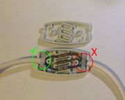
The only way to safely join two flexible mains leads is with an in-line screw terminal connection box. This has a cable clamp at each end which must be used to clamp the outer insulation, not just the inner wires.
Electricians often use a circular junction box without cable clamps, but this is only acceptable where all the cables entering it are secured along their length with cable clips, often nailed to a joist.
Choc block connectors
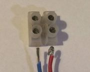
These come in strips which can be easily cut according to the number of wires you need to connect. They are useful for connecting low voltage wires but offer no form of cable clamp so should only be used for mains if you can ensure that the cables cannot be strained. They contain a hole between each pair of connectors, which you can use to screw them down to a firm base.
Choc block connectors come in various sizes such as 3A, 5A, 15A etc., but the only important thing is to ensure that they are big enough to take the wire, and more importantly, the wire is big enough to be gripped by the screw. You can always strip a little extra insulation and fold the wire double to give the screw more to grip.
Provided space allows, these connectors can be useful when replacing a thermal fuse which might be blown by the heat of a soldering iron. However, you may have to remove the housing, often made of soft plastic which may melt before the thermal fuse trips.
Spring terminal connectors
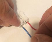
There are several types of these, and they can be used to make a quick and easy connection without any tools (except for stripping the insulation). They are often used for loudspeaker cables and in model train sets, providing a simple way for connections to be made or removed as often as needed. Applying solder to the bare end of stranded wire is helpful.
Wago connectors are a common proprietrary form of spring connector, coming in several different types. They are designed for commoning two or more wires, for mains or for low voltage use. Some have a lever to lift or to press to release the spring, but with others, you just push the wire in, and there's no visible means of releasing it. The trick with these is to twist the wire back and forth while pulling it firmly.
Soldering
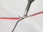
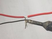
Twisting the wires together and soldering is often the best method, but there are two ways of doing this. If possible, you should twist the wires in-line before soldering as this makes a stronger (and neater) join than twisting the ends together. This requires a greater length to be stripped of insulation and can be tricky if the wires differ in diameter, or if one is stranded and the other solid.
The wires need to be clean in order to make a good joint. A little extra flux from a flux pen never does any harm and often makes it easier if the insulation has not been freshly removed. In the case of enamelled wire, the enamel needs to be scraped or burnt off. If a little remains it often won't matter and may melt with the solder. In fact some wire enamels are "solder-through" and designed to melt with the solder, but an initial scrape to get it started usually helps.
Soldering headphone leads
Headphone leads use a special kind of ultra-flexible wire consisting of many individually enamelled strands of fine wire. The three connections for stereo headphones or four for a stereo headset use different coloured enamel. You will need to separate the strands of each colour.
The enamel may be designed to melt in the solder but it often helps to start it off by gently scraping with a knife, trying not to break any of the strands as you do so. Alternatively you may be able to burn off the enamel in a flame.
Heat shrink solder sleeves
A simple solution if you don't have a soldering iron handy is to use heat shrink solder sleeves. These contain a ring of low temperature solder in the centre of a heat shrink tube. Make sure the stripped ends of the wires are clean so as to accept the solder. Pass one wire in each end so that they cross over in the solder ring, then simply apply a heat gun. This simultaneously melts the solder and shrinks the sleeve to insulate the join.
Crimping
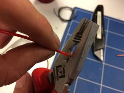
Crimping is both quick and easy, and makes a very reliable join, creating microscopic welds between the wire and the connector. But it does require the correct crimp connectors and crimping tool to make a good join. A crimping tool and a selection of crimp connectors are not expensive.
Crimp connectors come in several colour-coded sizes and it's important to use the right one. Too small and you won't be able to insert the wire, or too big and it may not be gripped properly. In addition to in-line connectors, an assorted set will usually contain a variety of spade, ring and bullet connectors as widely used in auto electrics.
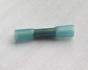
Some crimp connectors such as the one illustrated have a heat shrink sleeve. This can be recognised by the noticeably larger diameter of the sleeve at the two ends. When shrunk with a heat gun this seals around the wires at each end (provided they're not too thin), giving extra protection to the two wires being joined.
Another type of crimp connector has a blind hole into which both wires to be joined are inserted together.
N.B. for safety, always give a crimp connection good tug after making it to ensure it's a good one.
DIY crimping
Standard crimp connectors most commonly come in the larger sizes used in auto electrics, but these may be too large for some of the wires used in domestic electrical appliances and gadgets. An example is if you need to replace a wire-ended thermal fuse in a hair dryer, steam iron or kettle. Soldering may not be advisable as the heat from the soldering iron may cause the replacement thermal fuse to blow.
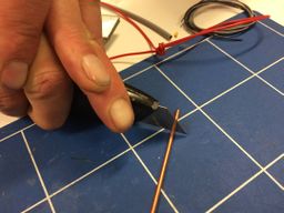
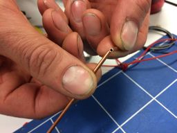
An alternative is to use narrow gauge copper or brass tubing as available from model making suppliers. Choose a size into which the wire fits comfortably. Cut a short length by rolling it on a flat surface under the blade of a craft knife to score it and then snap it off. Insert one wire into each end and crush the tube onto each wire with a pair of fine-nosed pliers or blunt wire cutters (but if you use wire cutters, take care not to cut into the tubing).
N.B. The tug test is arguably even more important with a DIY crimp.
Insulation displacement connectors
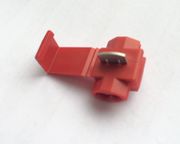
Scotchlok connectors contain a piece of metal which cuts through the insulation and bites into the copper conductor. They are commonly used in auto electrics for splicing into power wires in order to supply after-market accessories. They contain two holes for two wires, one open at the side allowing it to be slipped over an existing wire, and the other a blind hole to take a lead to the accessory. Squeezing it with a pair of pliers causes the metal piece to cut through the insulation of both wires and make the connection. Folding over the flap allows you to lock it closed.
You could equally use one of these to connect the ends of two wires, but you must use the right size for the wires you are connecting in order for it to cut fully through the insulation whilst not damaging the copper wire inside.
Insulating your connections
Some types of connector are self-insulating, so long as none of the uninsulated wire is exposed, but with others you will usually need to provide some form of insulation.
- PVC tape is the simplest and easiest but not necessarily the neatest. NEVER simply bind up a cracked mains lead with PVC tape.
- Heat shrink sleeving is an excellent method. It comes in a variety of sizes and colours, pre-cut or in a continuous length. Choose a size which is no more than twice the diameter of the joint you need to insulate, and don't forget to slip it onto one of the wires before you join them! If soldering, keep it away from the iron. Once you're ready, slip it over the join and heat with a heat gun until it has fully shrunken. If you don't have a heat gun to hand, you can hold it very close above a soldering iron and it should shrink slowly, but be very careful not to let it touch the iron.
- Sugru can be used to insulate a join as described above, such as in a headphone lead, but don't rely on it alone to provide strain relief. If you need strain relief then one solution would be to knot the lead either side of the join to give the Sugru something to hold onto.
- The earth wire in the type of mains cables designed for permanent installation is often uninsulated. Green and yellow striped sleeving is available to slip over this within a mains socket or wall switch to prevent it touching a live connection. This will sometimes be useful in other circumstances, but avoid using it where might confuse the next repairer into thinking it's an earth wire when it isn't.
